|
This is version 0.9.2 of the English MIDI introduction page, but I will come by, once in a while, and update it. I will start my Midi page with a text that I wrote to a Roadie course in 1997, when I was a student
in an unemployment project. The teacher, who was one of the most talented soundmen in Denmark, did not
think that he knew enough about MIDI to teach it to the class. I insisted however that the topic was
relevant,( a nice word from the good, old days) and I was instructed to make a presentation to the class.
When Martin read paper, he could well see that it was a lot more advanced than he had expected, and he
believed that no one else in the class would comprehend much of what I had written, so my writing was
delivered to the class members and then passed by in silence. The other students were not interested in
technology and binary number systems, but they were good at smokeing marijuana and lifting heavy gear.
It is now time that I reveal my self and confess that I am the source. I have been so bold as to copy text from the Soundcheck.dk page, with all the html tags that they have added. This way, I have saved a day of typing and formating the text. I have now refined the text further and added the original artwork from "The Big MIDI Book", so that readers, hopefully, can get the full benefit of my original work. Larsen's illustrations are black and white line drawings, and they are copied with author's permission, while I have produced the colored images myself.
From here, I will send a big THANKS for the openness that Lars Ekström has
shown in relation to letting me use his material. I hope that I have been worthy, of the trust
he has shown in me.
This page is much more interesting, if you move your pointer over pictures.
Midi-introductionThe purpose of this text is to give a general introduction to the MIDI stystem and how it is used. In addition, I will take a close look at MIDI time codes and what they do. I will, if I have time and energy, be going into greater detail about how individual codes are designed and what happens when they are sent and received, on the bit/byte level.
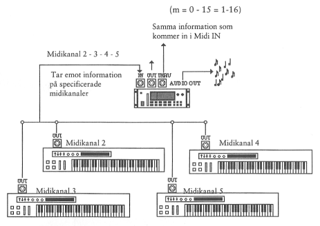
The MIDI-systemIs able to send information on 16 channels on each connection. This is done by tagging each data package with a channel number. When a MIDI device receives data, they will only respond to the data that is encoded with the correct channel number. MIDI has 4 different MIDI modes (states) each of which have their advantages and disadvantages. They decide which channels are received and how many notesthat can be sent to the reciving device on each channel. There are no real names for these modes, so as to avoid confusion it is best to remember the number.The following terms are used:
This is different MIDI modes:
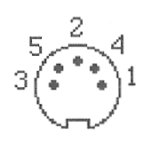
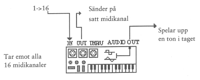
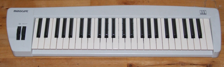
MIDI devicesmay be recognized by having one or more female DIN connectors marked with MIDI IN, MIDI OUT and MIDI THROUGH. On some MIDI devices, there are several connectors for MIDI OUT or MIDI IN. Some of these devices can send or receive 32 channels (two connectors).MIDI can only send data one way for each cable. A MIDI system may be associated with four types of connectors:
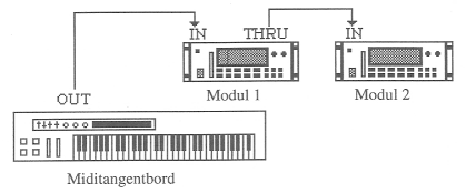
By taking the signal from the MIDI THROUGH and send it into the MIDI IN, you can create chains of devices that receive the same data. It is recommended that you do not connect more than five devices in a series, because there will be a delay of more than 30 milliseconds (which is the limit for what the human ear can distinguish).The MIDI-standard has no limit on how many devices can be connected together. The only restriction is where MIDI's speed problems become an audible nuisance. 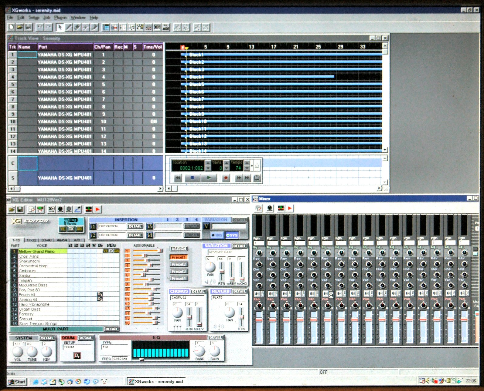
(See also MIDI switching equipment) The computer has become the core of any major MIDI system. The computer can not send and receive MIDI signals. Therefore, a MIDI interface can be fitted on the computer seriel connection witch usually has MIDI IN, MIDI THROUGH and several MIDI OUT. Another option is a PC to MIDI cable that is fitted on the Joystick connection on the Soundcard. From the computer, the other devices are controlled using a sequencerprogram. Here one can both receive, store, edit, play, and much more. The three types of Keyboards:
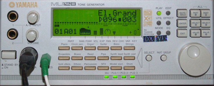
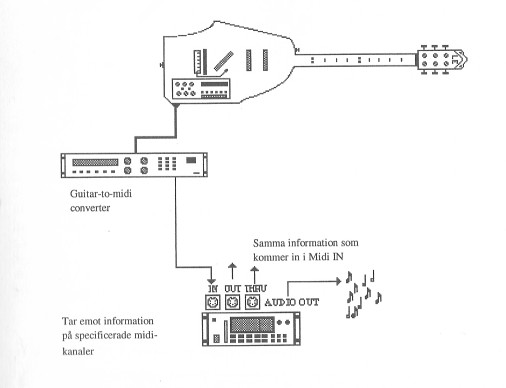
MIDI sound modules are, in practice a synthesizer or sampler without a keyboard. It can receive via MIDI IN and somtimes have a MIDI THROUGH. It can also play many sounds and instruments simultaneously and, for home use, it is often connected to a computer with a cequencerprogram and a MIDI keyboard. Drum Machine is an essential MIDI device containing a sequencer that can be programmed for different rythm patterns, that can be played with repetitions, variations, and fill in's, so we can have all the necessary rhythm to support a music number on one machine. Drum machine has its own sound module with samples from a large selection of drum sounds. Some models have pads (large buttons) that you can play directly or use for programming new rythms. It was the main instrument in disco music and in recent years dance music'en taken it to its fast beating heart. It is also used a lot in studies to keep the rhythm when you get tired of listening to the drummer himself or if he is drunk. And then of course for synchronization of sequencers and other MIDI equipment. Eventually, you can get almost all types of instruments to MIDI. First came the synth, but the MIDI guitar soon followed. This could be made with a sensor behind the strings and through some electronics, guess what note was being played and forward the corresponding MIDI code. It could only understand half tone jumps and if you bended the string, did vibrato or chords, it would be a mess. Later special MIDI guitars (as Synth AX costing a tens of thousand £) was made, but they still can not replace all the possibilities of a great guitar, all the musical expressiveness it has to offer and will always sound like "MIDI". After some time, many MIDI wind instruments(like Yamaha WX7 and Akai EWI seies) appeared, that used a blow-sensitive mouthpiece to simulate the real wind instruments in very convincing fashion. This makes it posible for a flautist to play on various wind instruments via midi without having to learn different playing techniques and he/she can also have fun with all sorts of other synth sounds from a sound canvas. In addition, a host of other machines in connection with sound reproduction, can be controlled by MIDI data. FX-boxes can be programmed to respond to the program/sound change message or the NOTE-ON messages. A particularly important possibillity in this regard is the phenomenon of "Bulk Dump", where all settings can be sent out on MIDI and stored on disk. Then, when you come back and some dumb dude has tampered with the gadgets, you can just garb the disk and copy it all back. Tape recorders can receive remote control orders with time code and even fast-forward and rewind to a preset point on the tape, so you can sit down, in peace and tranquility in your comfortable chair and concentrate on mixing.MIDI switching equipment
The MIDI languageI will now take a closer look at the core of the MIDI language and what it can do for us.
MIDI is based on computer technology and therefore it is working with numeric codes
(Bits, Nibbles and Bytes). In order to understand this, it is unfortunately necessary to
understand the binary number system. I don't want to waste precious time on a complete
totorial, so here are a few facts and those who are interested, can then bury themselves
in the subject on their own. A Crash course in binary numbersA Bit is a 1 or a 0. In principle, they are put together in the same way as 10-number system, where a digit that is furthest to the right counts as ones and the next, to the left of the said digit counts the smallest value which can not be counted for by one cifer. (Can you follow me?)In our system, based on the number 10, we can count to nine and the next will be one zero. like this: 10 In the binary system can count to 1 and the next number is written as follows: 10 (= 2). Every time you move one space left, a one-digit in this place equals to twice the value. So from right to left, a one correspond to 1, 2, 4, 8, 16, 32, 64 and 128 A zero in the same seats will always be equal to 0 wherever it stands. To find the equivalent value in 10-number system, you add the values of the 1's acording to their respective places. eg. bin 10101010 = 128 + 0 + 32 + 0 + 8 + 0 + 2 + 0 = 170 A byte (8 bits together)is the basic unit of information in this system and can take on 256 different values (0->255)(00000000->11111111). Half a byte is called a nibble and consists of four bits, which can take on 16 values (0->15)(0000->1111). Additionally, i will mention the first and last bits in a byte 11111111 . They are called MSb og LSb (note the lowercase b): MSb (Most significant bit, is the leftmost), LSb (Least significant bit, is the rightmost). If two bytes (groups of 8 bits) are side by side, the left will have a value 256 times higher than, the one on the right, because you can count to 256 by one byte. Therefore, we also have special names for these two entities. (With a capital B) MSB (most significant byte = most significant byte, left) LSB (least significant byte = least significant byte, right). And now for the fun. What kind of services does the MIDI language have offer
When sending a MIDI message that is encoded with channel numbers, the first byte should always be a status byte, indicating the type of data that comes after. A status byte is composed of two Nibbles: 1 status nible, that always have one as the most significant bit MSbit (far left) and Nibble 2, indicating a channel number. It looks like this in binary code:
Generally a status byte is written on the form:
The Byte's will look like this for the different channel-messages:
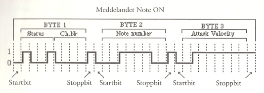
------------------------------------------------ After a status-byte, one, two or more data bytes follows, depending on it's status type. MSb,the first bit, on a data byte is always 0 (Example: 01111111 = 127 is the highest value). Note-On:
Data-byte 1: A normal MIDI piano with 88 keys sends 21-108. 60 is normally equal to C1 Data-byte 2: Indicates how quickly a key is pressed (gives the initial level of a note, attac). Here is a table showing the levels that are commonly used in music systems, together with the corresponding midi values.
Note that if the Attack Velocity is 0, it will be perceived as a note-off message. This makes it possible to send in "running mode", where a status byte is followed by many packets of data bytes, until a new status byte is send, with the MSb = 1 is sent. The Data byte's are hereafter interpreted, based on the format belonging to the new status-byte. Note-Off: Sent when a note ends on a MIDI instrument.
Data-byte 1: same as Note-On Data-byte 2: A faster release rate (high value) often makes the note fade faster, but can be programmed to do anything, using the settings in the device that receives the MIDI data. Polyphonic Key Pressure/After touch:
Data-byte 1: Som Note-On Data-byte 2: Sends a new value for each key pressed down, as soon as the pressure on any key changes. Exists only on expensive keyboards. This is Sending a lot of data and can therefore cause problems if many instruments are using the same MIDI connection. A common use for this is to control the level of vibrato, by changing the pressure after a key is pressed. Channel Key Pressure:
Data-byte 1: Same as Note-On, but if more keys are pressed, the value of the last key is send. Data-byte 2: Sends a new value for all keys pressed (on the channel) as soon as the pressure changes. Usually the highest value is send, but some of the better keyboards calculate an average, this is called plastic dynamics. Sends a lot of data and can for example be used for vibrato control by changing the pressure after the key is pressed down. Program Chance:
Data-byte 1: The new program number. On keyboards and sound modules this feature is used to switch patch/sound. There has been a long time without any standard for what sounds are on the program places, but Roland has attempted to introduce a standard called General MIDI, GM (General MIDI System See copy of page 73-74, not available in English, sorry), that now has become a de facto standard. Most other manufacturers have joined them, but it toke some time before this part of the MIDI system became standard. An FX machine receiving a Programe change message, may change the effect program while other MIDI machines can do other things, such as turning on a coffee machine or change the CD on the CD player(some time in the near future?). It may be a problem wether the first program is called 0 or 1, so you can get sound 15, when you ask for number 14. It is alleged that some machines can start further up in the series of numbers, but I have not seen that. Control Chance:
Controller ID Nr.(Databyte 1): Indicates the control value to be changed. (see attached copy of page 26-27, not available in english, sorry). These values correspond to a button, pedal, effect wheels or somthing else, that may be adjusted in real time by a sound or a program in a MIDI machine. Controller Value(Databyte 2): The new value for the controler. There are three types of controls:
These controllers are send to a particular channel:
Nr. 121-127 Channel Mode Messages:
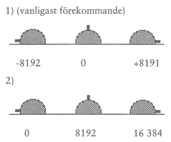
Pitch Bender:
Databyte 1(LSB): Least significant byte of PB.-wheel position. Databyte 2(MSB): Most significant byte of PB.-wheel position. Together they provide for 16,384 values. Unfortunately, these values are transmitted by two systems, both used. 1st Rest position is indicated by 0 and values ranging from -8192 to 8191st 2nd Rest position is indicated by 8192 and values ranging from 0 to +16383. If you can find out which model the system uses, this can function to raise or lower the tone within the number of semitones that has been programmed in the "sound" settings. MIDI Time Code Systems: MIDI Time Code (MTC): TMC is designed to work with video-/film-equipment and therefore counted in hours, minutes, seconds and frames (24, 25, 30, 30drop). Frames indicates how many images per second split up in. 30drop is a speed which is 29.97 fps. second, so you drop two additional farms in every 10 minutes in order to get the time to fit exactly. Messages are sent four times each. frame, ie 120 times PPR. second at 30 f/s coding of the cues transmitted are quite complex and I will not go into detail with it. Full Messages: It is used when the main device for example a VCR rewinds the tape and sends the same information on hours, munutter, seconds and frames (24, 25, 30, 30drop) but only once each frame. A data message is 10 bytes, but does not burden the system as much as MTC. When it arrives at the desired location, it waits for the other machines to report that they have also reached the same time code, then it starts sending MTC again. SMPTE (Society of Motion Picture & Televition Engineers): This time code was developed by NASA to synkronisre images from different transmitting stations. Since it has become the dominant standard in radio, video and film. SMPTE splits up time in hours, minutes, seconds, frames (24, 25, 30, 30drop) and Bits (80 frame parts). It uses 80 bits for all values of one times (one time packeage). The code consists of one square oscillation whose clock frequency is normally kept within 900hz.-2400hz. Experts call SMPTE, LTC (Longitudinal Time Code). One problem with SMPTE is that you can not run slower than 1/10-1/20 of normal playback speed without the code becomeing hard to read, this is however usually only disturbs readout of some the Frame-bits and is corrected when the next correct reading the time is decoded. If you record and play SMPTE, never use any filtering or noise reduction, because it destroys the shape of the sqare. To succed in getting the three aforementioned cues to communicate with one another, some clever people has developed DTL (Direct Time Lock) and DTLe (Advanced Direct Time Lock) which is different conversion languages, that translates codes between SMPTE and TMC/Full Messages. They are available as software for computers or as hardware boxes. MIDI Cueing Messages (MTC): These codes are part of the MTC system and used to send control commands to devices such as Studio tape recorders, DVR etc. This is list of some of the functions that can be sent: Set/delete Punch in points Start from here when synchronizing recording Set/Delete Punch Out points. end here when synchronizing recording Set/Delete Event starting points. start event (likesound effect) here Set/Delete Event end points. End Event (like sound effect) here Set/delete cue points anywhere you want to be rewind to. 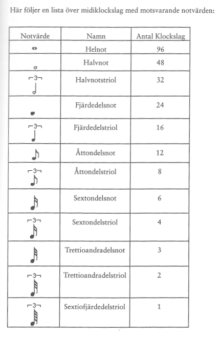 MIDI Clock:
This system counts beats and music notes, in the sense that, the system clock(Usually) send 96 MIDI Clock messages for each quarter note. There should be a MIDI clock master in a system. This copuld be a computer that controls one or more sequencers. Once they receive the signal, it adjusts how quickly they send tune data, so all MIDI devices plays the melody at the same speed. (See Appendix. Copy of page 47) To be continued! |
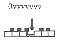
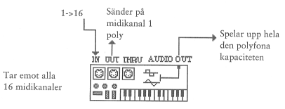 Omni On / Poly (MIDI Mode 1):
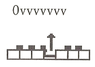
 Omni on/mono ( MIDI-mode 2 ):
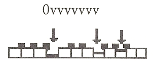
 Omni off/poly ( MIDI-mode 3 ):
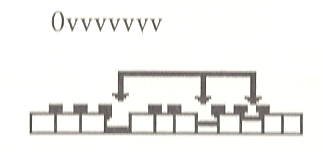
 Omni off/mono ( MIDI-mode 4 ):
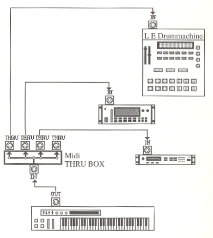 MIDI THROUGH-box recieves a MIDI IN signal and makes copies to multiple MIDI THROUGH outputs.
This is very useful for larger setups with multiple MIDI devices and it helps in avoiding the
delays that comes because of serial linking. This also helps to make the layout clearer.
MIDI THROUGH-box recieves a MIDI IN signal and makes copies to multiple MIDI THROUGH outputs.
This is very useful for larger setups with multiple MIDI devices and it helps in avoiding the
delays that comes because of serial linking. This also helps to make the layout clearer.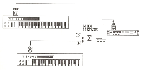 The MIDI merger-box has several MIDI IN connectors and one or more MIDI OUT connectors.
With this device you can put several keyboards and computers in the MIDI IN connectors,
and get a well formated and error free MIDI signal from the output. The output can then
be connected to a MIDI sound module or what ever. You must make sure that you send your data
on different MIDI channels, in order to ensure that data from various devices are not mixed.
The MIDI merger-box has several MIDI IN connectors and one or more MIDI OUT connectors.
With this device you can put several keyboards and computers in the MIDI IN connectors,
and get a well formated and error free MIDI signal from the output. The output can then
be connected to a MIDI sound module or what ever. You must make sure that you send your data
on different MIDI channels, in order to ensure that data from various devices are not mixed. MIDI switcher (mechanical) or MIDI patchbay (electronic) has several MIDI IN connectors and
multiple MIDI-OUT connectors. The idea is that you can select which inputs are connected to
the outputs. In addition, the MIDI patchbay's often makes it possible to filter MIDI data so
that SysEx messages and sound change messages are filtered or translated.
MIDI switcher (mechanical) or MIDI patchbay (electronic) has several MIDI IN connectors and
multiple MIDI-OUT connectors. The idea is that you can select which inputs are connected to
the outputs. In addition, the MIDI patchbay's often makes it possible to filter MIDI data so
that SysEx messages and sound change messages are filtered or translated.